Case Presentations
“Endodontic Microsurgery of an Anatomically Challenging Zone Using Dynamic Navigation” By Dr Paula Villa, Colombia, 2020
Background
Enhanced magnification and visualization, innovations in instrumentation, new sealing materials and the incorporation of soft and hard tissue augmentation practices have brought Endodontic Microsurgery (EMS) from a last resort procedure to an integral part of endodontic retreatment.1,2 The retreatment of a failing root canal treatment is fraught with potential complications. The removal of cast posts (size and length can potentiate fracture)3 distinguishing bonded fibre posts from the surrounding dentin,4 removal of separated instruments5 negotiating blocked canals,6 circumventing ledging and a myriad of other factors can complicate removal of the residual bio-load and impede resolution of periradicular pathosis.7,8. Where possible, retreatment alone would be the treatment option of choice, however, where retreatment risk factors are high, EMS is the most viable option, far more so now than prior to the transition to microsurgical protocols.
Contemporary EMS protocols provide for minimal flap size, small osteotomies and resections perpendicular to the long axis of the root. These minimally invasive practices reduce morbidity, accentuate more rapid healing, minimize the size of the retro-preparation and the number of dentinal tubuli exposed.9 Magnification and illumination have lessened the risk of damage to anatomic structures such as the IAN, maxillary sinus and the greater palatine nerve and artery. Given the inability to visualize the surgical site in three-dimensions, the possibility of procedural error remains, thus impacting on treatment options.10-13
Recently, Dynamic Navigation technology has been used in EMS to guide cutting instruments, including piezotomes, in real time, to perform osteotomies and apicoectomies. Dynamic Navigation systems map the patient’s jaws to their cbCT scan by trace registering landmarks on teeth of the jaw to be treated. The system’s stereoscopic camera recognizes optical markers attached to the jaw to be treated and the instrument to be used and monitors the drill or saw position during the surgery. Unlike static navigation guides, Dynamic Navigation procedures are not constrained to a predetermined path, there is no risk of distortion as a complication of the guide fabrication, and the inability to work in restricted areas of the mouth due to the bulk of the guide is obviated.
Dynamic navigation enables adjustment of the osteotomy pathway and the angle of the root section during the EMS procedure. The clinician follows the surgical instrument’s movement in three-dimensions on the computer monitor and assesses the surgical site through the microscope oculars. This case report presents the use of Dynamic Navigation to avoid damage to the Schneiderian membrane of the maxillary sinus while performing EMS in an anatomically challenging space.
Case Report
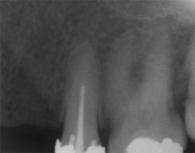
A 50-year-old male patient presented with moderate pain associated with a previously treated maxillary right second premolar (tooth #1.5). The medical history was non-contributory. The tooth had been endodontically treated and restored with a cast post/core and full crown. The patient’s scan (cbCT) revealed two separate roots, an intact buccal plate and an apical lesion associated with the palatal root (Fig 1). The tooth was moderately sensitive to vertical percussion, periodontal probe depths and mobility were within normal limits. The diagnosis was symptomatic apical periodontitis associated with a previous root canal procedure. After consultation, the patient chose to have EMS treatment done with Dynamic Navigation.
Fig 1
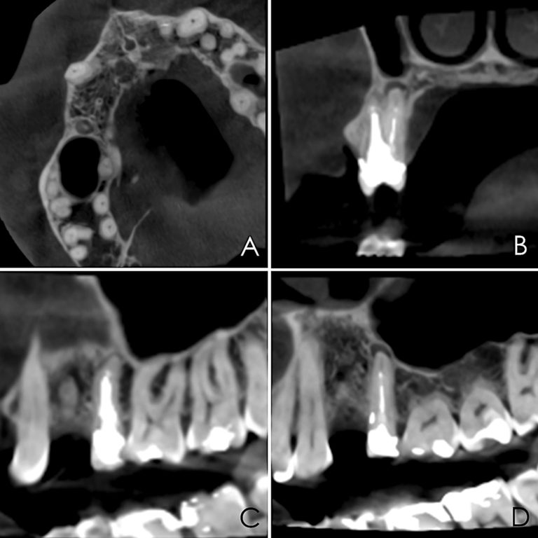
The proximity of the palatal root apex to the sinus floor raised the issue of an existing sinus perforation or the risk of iatrogenic creation. Dynamic Navigation enabled real-time feedback of the position of the instrument tip in a z axis as it accessed the palatal root apex and the floor of the sinus.
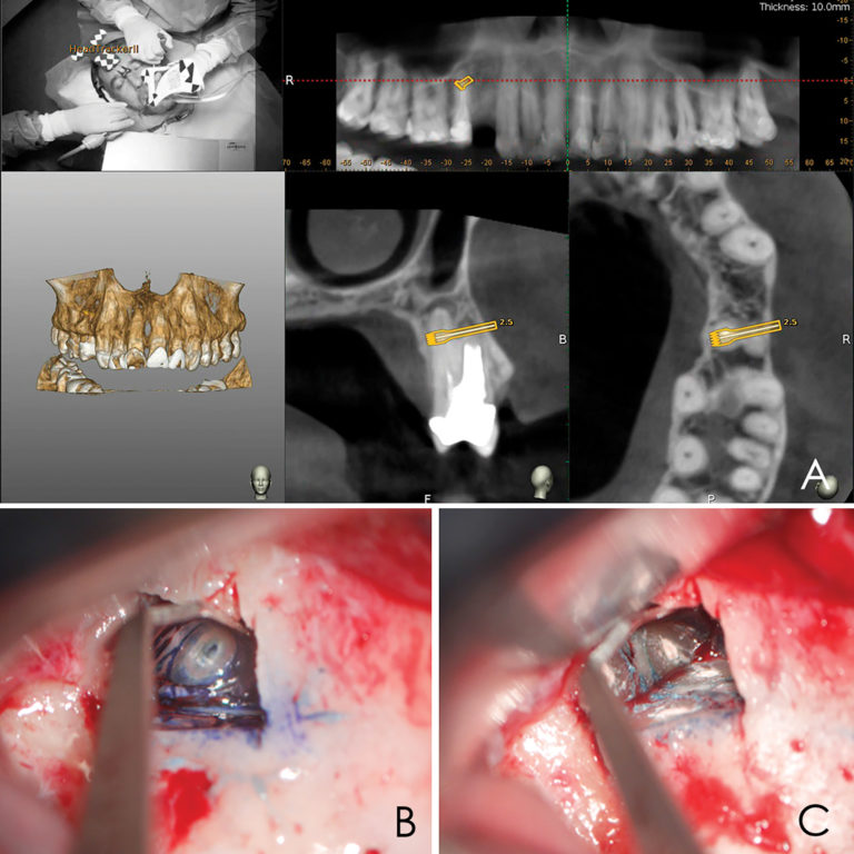
Lidocaine 2% with 1:80,000 epinephrine (New Stetic, Guarne, Ant. Colombia) was used to achieve profound local anesthesia and a full thickness mucoperiosteal flap with a vertical releasing incision was elevated. (Fig 2A).
Fig 2
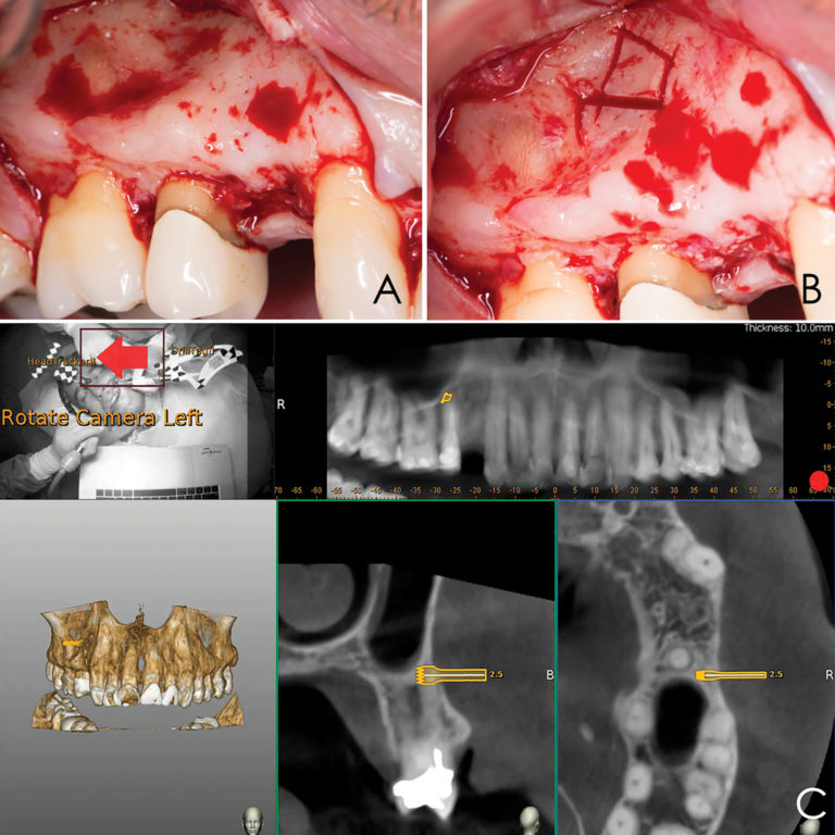
Three landmarks (up to 6 can be used) were marked on teeth displayed in the patient’s scan in a non-colinear array. A Head Tracker (optical marker) was secured to establish jaw position, a tracer tag attached to a tracer tool and a stentless trace registration of the maxilla done by creating a cloud of points around the landmarked teeth thus accurately mapping the avatar maxilla on the cbCT.
An accuracy check was performed to verify the trace registration, a drill tag (optical marker) was secured to the Piezotome® Cube handpiece (Acteon group, France) by an adapter, the LC2 saw secured to the handpiece and the saw tip calibrated. The Dynamic Navigation software algorithms enable the micron tracker (stereoscopic camera) to identify the avatar saw tip as it cuts the periphery and depth of the cortical window (Figs 2B, 2C). The position of the saw at the periphery of the palatal root resection can be precisely tracked thus preventing a sinus communication (Figs 3A, 3B). The retro-preparations were done using a E30RD ultrasonic tip (USA – NSK-Nakanishi International).
Fig 3
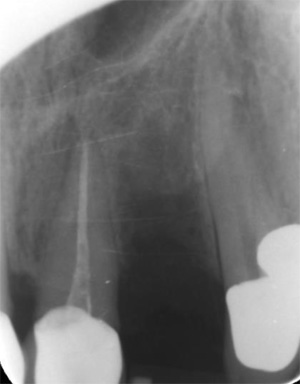
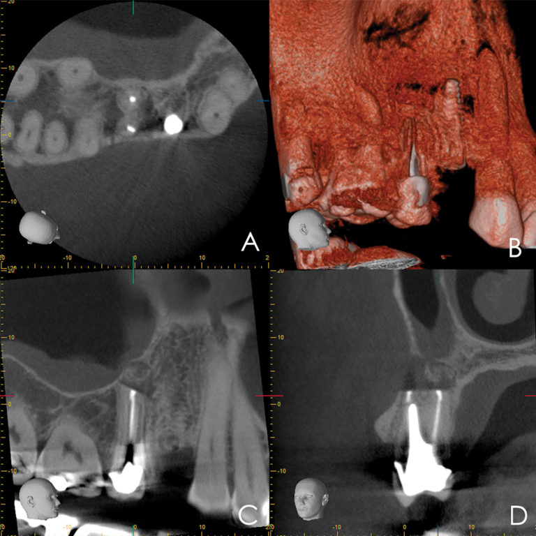
EndoSequence BC RRM Fast Set Putty (Brasseler, Savannah, GA) was used as the retro-sealing material (Fig 3C). Radiographs were taken to confirm the density and position of the retroseals. The post-surgical cbCT confirms the precision of the saw cuts resulting in accurate resection of both roots without complications ensuant from an iatrogenic tear of the sinus membrane (Fig 4).
Fig 4
Discussion
Dynamic Navigation has been shown to be more accurate than freehand and static navigation in surgical implant placement.14 Its effectiveness has been demonstrated for the removal of foreign objects from the maxilla and mandible, repositioning of the IAN and removal of pathology with minimal hard and soft tissue damage.15-18
Piezosurgery is a relatively new surgical technique. Its major advantages include; precision, ease of curvilinear osteotomy, less trauma to soft tissue, preservation of neurological and vascular structures, reduced hemorrhage, minimal thermal damage to the bone, and improved healing. Piezoelectric bone surgery has been demonstrated to mitigate complications during maxillary osteotomy procedures, such as oroantral communication.19-23 Vercellotti et al. introduced the piezoelectric bony window osteotomy as a simplified technique for sinus elevation24. Due to the cessation of the surgical action of the piezoelectric scalpel when it comes in contact with nonmineralized tissue, there is a reduced risk of iatrogenics25. In conjunction with Dynamic Navigation, Piezosurgery allows for the creation of a cortical window which accurately approximates the pathology about the root apices.
Conclusion
Dynamic Navigation is an exciting and promising adjunct for enhancing positive EMS outcomes in contrast to the efficacy of static navigation guides. The real-time feedback feature of Dynamic Navigation technology mitigates risk in areas close to anatomic structures. Selective and controlled osseous dissection is enhanced. The ability to alter the surgical pathway provides for an improved margin of accuracy and degree of safety. Its use in other aspects of EMS are being evaluated.
Oral Health welcomes this original article.
Photographs: Figures 1, 2, 3 Brian Waters. Figures 4-11 Sejaan Arora.
About the Authors
*Corresponding author: Prof. Paula Andrea Villa Machado, Laboratory of Immunodetection and Bioanalysis, Faculty of Dentistry, University of Antioquia. Calle 70 N° 52-21, Medellín, Colombia. Phone number: (574) 2196735 Fax: (574) 2631230. e-mail address: [email protected], [email protected].
Kenneth S. Serota has been active in online education since 1998, he is the founder of the Endodontic forum ROOTS and the interdisciplinary Facebook forum NEXUS. Dr. Serota is a clinical instructor in the University of Toronto postdoctoral endodontics department. He is the social media and marketing director for Navident Dynamic Navigation.
Dr. Felipe Restrepo is an Associate Professor at the Universidad de Antioquia teaching their postgraduate level students in endodontics and also Director of the Dental Emergencies Diploma. Dr. Restrepo has authored scientific articles in peer-reviewed journals. He can be reached at [email protected]
“Dynamic navigation by innovative registration” BY Dr Ricardo Henriques, Portugal 2018
Background
3-D implant planning and mapping that plan to the real surgical environment are two important steps in implant rehabilitation.1,2 Misplaced implants can create difficult aesthetics, functional and biological problems and can result in implant loss.3–5
There are three ways to transfer a planned implant’s position into the real patient’s jawbone:
- mental navigation, so-called freehand navigation,
- static navigation using surgical templates,6 and
- dynamic navigation using a stereoscopic camera.7,8
The freehand approach is totally dependent on the surgeons’ experience, skills and mindset during treatment and creates the highest deviations compared to the other approaches.2
The usage of surgical templates provides a higher accuracy compared to freehand surgery, but has a few limitations, such as the inability to modify the plan once the surgical template has been manufactured. Surgical templates require longer drills which can make their use quite difficult or even impossible. Other concerns are irrigation issues and incompatibility with advanced surgical protocols.
Dynamic navigation is, at present, the most effective way to transfer the planned implant’s position to the real patient as it guides the surgeons’ motions using real-time feedback. It is especially useful to reduce flapped procedures with the advantage of improved soft-tissue healing, patient comfort and reduced bone resorption. Dynamic navigation allows planning modifications at any time, even during treatment, and can be used in cases with limited mouth opening or in combination with osseodensification drills.
The dynamic navigation concept using trace registration
In this approach, the patient’s jaw and the surgical drill’s location are being tracked by the navigation system’s tracking camera, using special tags affixed to them. To correspond between the physical patient’s jaw and its on-screen cone beam computed tomography (CBCT) scan representation, the tag installed on the patient’s jaw must be mapped with the CBCT scan. The mapping of the trackable jaw tag to the CBCT scan is called registration. Traditionally, the patient would have to be CT-scanned with an artificial radiographic marker, also known as “fiducial”, which has to be later identified in the CT images by the navigation system’s software in order to enable the registration.7
The innovative trace registration method (Navident, ClaroNav) eliminates the need for this artificial fiducial body to be present in the image, by replacing it with natural high-contrast surfaces, such as tooth crowns or abutments already present in the image. Therefore, it eliminates the need for patient exposure to a new dedicated CT scan with a fiducial. The level of radiation is an important issue in diagnosis.9,10 This new method also eliminates the need to have a special stent prepared to couple the fiducial or trackable tag to the jaw in a highly stable and repeatable manner, which was previously essential for the performance of accurate navigation.
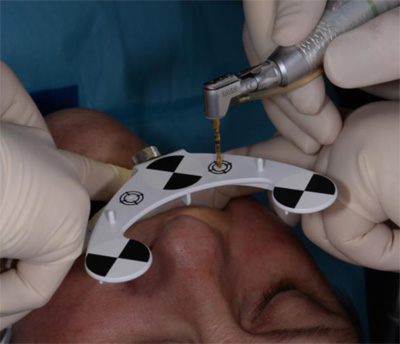
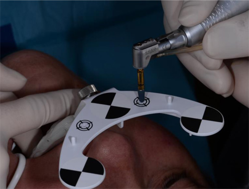
To treat the maxilla, a pattern tag, or Head-Tracker, is positioned on the patient’s head like glasses with contact points that don’t move with patient muscle contractions or lower jaw movement (Fig. 1). This ensures that the Head-Tracker maintains a stable relationship with the skull, and thus the maxilla. For the mandible, another pattern tag, called Jaw-Tracker, is temporarily connected to one to two teeth using dual-cure composite resin (without etching the teeth to allow for easy removal; Fig. 2). This Jaw-Tracker can also be used for the maxilla instead of the Head-Tracker.
The surgeon chooses four to six identifiable landmarks on structures which are rigidly attached to the jawbone (teeth, abutments) and are easily visible in the CBCT scan. In the next step, the surgeon traces a path on the surface of each one of the marked structures with a tracer tool, also tracked by the camera (Fig. 3). The system collects 100 points on each one of the traced structures, and optimally matches them to the CT image data to register the Head-Tracker or Jaw-Tracker, with the patient’s maxillary or mandibular CBCT scan, respectively.
Advantages of trace registration
The most important advantages of the trace based over the fiducial/stent-based registration method are:
- No need to design and fabricate a stent or guide in advance, eliminating the associated preparation time and effort, as well as the potential risk for inaccuracy due to improper seating of the stent during the scan or procedure.
- An existing CBCT scan can be used, there is no need for a special scan with stent and fiducial(s). The scan may be taken in full occlusion resulting in easier digital prosthetic planning.
- No stent or guide is in the patients’ mouth during treatment, allowing the same access space in the oral cavity during surgery as with a freehand approach.
Possible limitations
- At least four high-contrast structures fixed to the jaw bone must be available and accessible for tracing. These can be teeth, abutments, bone screws, orthodontic brackets and wires, or similar structures. With fully edentulous patients, regions of the jaw bone itself may be exposed and used as landmark regions.
- Each of the traced regions should not have changed in appearance or location relative to the jaw bone since the scan was taken. If guidance is critical and changes to the jaw such as changes in teeth position are a concern, a fresh scan prior to surgery is advised.
Case presentation
The treated patient was a 54-year-old female with a removable prosthesis, who wished to have a fixed solution. The patient was a non-smoker without medical problems. Intraoral examination revealed the absence of tooth #24 and bone resorption where the teeth had been extracted.
Planning procedure
A CBCT scan was taken without any radiographic marker (Fig. 4). The images were taken with a Carestream 8100 3D (Henry Schein). The field of view used was 80 x 90mm and a voxel size of 150μm. The exposition parameters were 84kV and 4mA. The images were analysed and converted into DICOM files and then converted into a 3-D virtual model by the Navident software. A virtual crown and implant were planned to have 2mm of buccal bone and a restorative space at the centre of the crown (Fig. 5). The virtual implant planning was then modified creating an angulation of six degrees in vestibular direction, so the surgeon would be guided to initiate bone preparation with a six-degree vestibular angulation (Fig. 6).
Surgical procedure
Local anaesthesia was performed in region #24 and aseptic and sterile conditions were applied to prevent infections. The Head-Tracker was positioned and inspected for stability. Trace registration was performed by marking four landmarks on teeth using a panoramic 3-D presentation of the jaw, then tracing the landmark regions with the tracer tool while the camera and software collected 100 points on each tooth (Fig. 7). Navident automatically registered the Head-Tracker with the patient’s maxillary CBCT scan based on the collected points.
In the next step, drill calibration and accuracy check were performed before the use of each drill. A small incision for a reduced flap was made. All osteotomies were performed at 800 rpm. The virtual implant angulation was pre-surgically modified six degrees in vestibular direction, so the osteotomy could be initiated on that angle. Next, the virtual implant was repositioned intraoperatively on the Navident software and the rest of the site preparation was carried out according to the final angulation with osseodensification drills (Fig. 8). The osteotomies were made with two angulations and tracked in real time and the same procedure was applied for the implant insertion. A cover screw was attached before the surgical area was sutured. The patient reported no discomfort during the surgery.
Postoperative evaluation
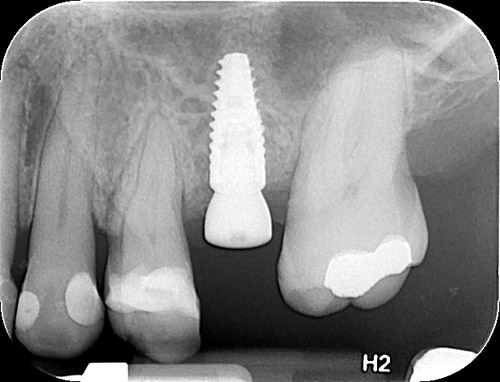
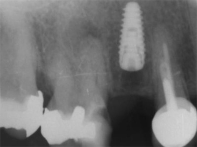
The patient reported no pain or swelling. Radiographic and clinical images were taken with a direction indicator screwed onto the implant. The postoperative evaluation showed that the position of the implant exactly corresponded to the virtual planning made beforehand (Figs. 9–14).
Conclusion
The patient benefited from a treatment with a reduced flap and precise implant placement using dynamic navigation technology with an innovative trace registration method. Trace registration in combination with dynamic navigation proved to be a valid technology for osteotomy preparations and implant placement. It does not require a dedicated CT with a radiographic marker nor the fabrication of a stent or clip. When clips or stents are difficult or impossible to use, or even in every dental patient case, trace registration can be the best solution for dynamic navigation implant placement.
References
1. Somogyi-Ganss E, Holmes HI, Jokstad A. Accuracy of a novel prototype dynamic computer-assisted surgery system. Clin Oral Implants Res. 2015 Aug;26(8):882-90.doi: 10.1111/clr.12414.
2. Block MS, Emery RW, Lank K, Ryan J. Implant Placement Accuracy Using Dynamic Navigation. Int J Oral Maxillofac Implants Surg. 2017; 75:1377-1386.
3. Umapathhy T, Jayam C, Anila BS. Overview of surgical guides for implant therapy. Journal of Dental Implants, 2015 Jan-Jun; 5(1):48-52.
4. Kate MA, Plaskar S, Kappor P. Implant failure: A dentist’s nightmare. J Dent Implant 2016; 6:51-56.
5. Palma-Carrió C, Maestre-Ferrin l, Peñarrocha-Oltra D, Peñarrocha-Dago MA, Peñarrocha-Diago M. Risk factors associated with early failure of dental implants. A literature review. Med Oral Patol Oral Cir Bucal. 2011 Jul; 16(4):514-517.
6. Borisov R. Radiological templates and CAD/CAM surgical guides. A literature review. J of IMAB. 2016 Jul-Sep; 22(3):1285-1295.
7. D’ahese J, Ackhurst J. Bruyn H. Immediate loading with dynamic navigation implant surgery. International magazine of oral implantology. 2015; 3:34-37.
8. D’haese J, Van De Velde T, Komiyama A, Hultin M, De Bruyn H. Accuracy and Complications Using Computer-Designed Stereolithographic Surgical Guides for Oral Rehabilitation by Means of Dental Implants: A Review of the Literature. Cl in Impl Dent Rel Res 2012; 14:321–335.
9. Dula K, Mini R, van der Stelt PF, Buser D. The Radiographic Assessment of Implant Patients: Decision-making Criteria. International Journal of Oral & Maxillofacial Implants. 2001 Jan/Feb; 16(1):80-89.
10. Uysal H, Basal N. Dynamic navigation in fully edentulous maxilla. International magazine of oral implantology 2017; 3:38-41.
Contact
Dr Ricardo Henriques
Private Practice
R. S. Martinho, 423 – R/C
4505-164 Argoncilhe, Portugal
[email protected]
"Dynamic navigation for precise Implantation in cases of critical anatomy" by Dr David Burgess, United Kingdom 2017
INTRODUCTION
Using the CBCT image as a map, dynamic navigation guides surgeons just like a GPS guides drivers. The clinician virtually plans where implants should be placed. During surgery, the navigation system dynamically tracks the drill and the patient’s jaw, providing guidance and visual feedback to ensure the implants are placed according to plan.
There are several advantages with dynamic navigation. The technology allows clinicians to place implants more accurately than free-hand. This results in improved safety and aesthetics, as it helps the clinician to anticipate and to avoid potential complications. Other advantages are the ability to have more minimal invasive treatments, which means less chair time, less patient discomfort and less recovery time. This treatment option has generally been seen as a ‘blind’ procedure in the past, but the ability to avoid delicate anatomical structures due to the real-time surgical feedback makes so-called flapless surgery a valuable option.
In the following case report, Dr David Burgess describes how using computer-guided dynamic navigation helped him overcome clinical challenges for dental implant placement in the lower posterior region.
Case Report
A 75-year-old male patient had endured a gap for five years, following removal of his lower left second molar, due to an acute apical infection. He was finding mastication increasingly difficult and sought advice about the treatment options available.
Planning for optimum implant positioning
As there was no tooth distal to the space, conventional fixed bridgework was not possible. The treatment options were either a unilateral single saddle lower partial denture or restoration of the space with two dental implants. The patient chose to have dental implant treatment as he did not wish to have any form of removable prosthesis.
What makes Navident dynamic navigation stand out is it precisely guides the surgeon to prepare and place the implant in a pre-determined position (Figure 1). This allows me to achieve greater accuracy and certainty than I have previously been able to, using conventional protocols. Whilst there is no physical guide, a simple scanning template (NaviStent) is used to hold the fiducial in place whilst taking the CT scan, and secure the jaw reference (JawTag) for the navigated osteotomy.
In this case, the Navistent was fabricated, the fiducial marker attached and a CBCT scan taken two weeks prior to surgery (Figure 2). The treatment plan was created immediately after the scan (Figure 3), with the patient present. He was able to see the proposed treatment displayed by the Navident software and appreciated that great care was being taken to achieve the optimum implant positioning, with minimal risk of potential complications (Figure 4). The patient was extremely impressed with, and reassured by, the state-of-the-art technology.
Confidence from continuous feedback Treatment was carried out under local anaesthesia. Prior to preparation of the implant sites, the simple Navident protocol for calibration and verification of the drill axis and drill tip was carried out. A crestal incision was made, with a minimal flap reflected. The software shows the drill position on the scan in real time, as it enters the jaw. This allows adjustments to be made, if necessary, whilst the site is being drilled. Two DENTSPLY ANKYLOS® CX 3.5mm diameter dental implants were placed sub-crestally in the lower left first and second molar sites, with implant lengths of 11mm and 9.5mm respectively.
Avoiding damage to the inferior alveolar nerve was a crucial factor in the treatment planning of this case. Access was difficult, due to the limited opening of the patient’s mouth. The issue was compounded by the plan to place an implant as distal as the second molar. These challenges were overcome using Navident’s continuous internal visual feedback, which gave me the confidence to use the optimum length of implant, whilst staying within a safe distance from the inferior alveolar nerve and avoiding post-surgical complications, such as paraesthesia.
Navident provided guidance for accurate implant location, even with restricted visibility and the drill being impeded by opposing teeth. Tactile feedback can often be reduced when using a physical drill guide. Dynamic navigation removes this obstacle. I was able to achieve the best buccal and lingual position of the implants, and their relation to each other and to adjacent teeth (Figure 5). This would allow for optimal shape, position and occlusal function of the final restorations.
ANKYLOS® Balance posterior sulcus formers were fitted and the incision was closed with simple interrupted sutures. There was no need for bone augmentation. Two to three months after surgery, the implants will be restored with ATLANTIS® custom-made CAD/CAM titanium abutments and screw-retained linked zirconia crowns.
The clinical outcome was excellent. The planned placement was restoratively driven and the implants were well positioned, with good primary stability. Having used the Navident dynamic navigation system for more than a year, I would not want to go back to preparing and placing dental implants without its 3D visual guidance. The patient was comfortable and reassured, with no post-operative pain, swelling, bruising or paraesthesia. He was delighted and, if he needed any implant treatment in the future, would insist on dynamic navigation.
About Dr David Burgess BDS DPDS MScConSed
David Burgess has been principal of Carbis Bay Dental Care in Cornwall since 1988 and has placed over 2,000 implants. Throughout his career, David has striven to combine clinical perfection with the ultimate in patient care. He has been a willing pioneer of new technology, particularly in the field of digital dentistry. David was the first UK clinician to introduce the Navident dynamic navigation system into his implant treatment workflow, with the objective of achieving a higher degree of precision and greater patient comfort.
David Burgess is also a member of the Dynamic Navigation Society as a Master Clinical Trainer, providing courses for implantologists who wish to experience how dynamic navigation can help to simplify their digital workflow. More information can be found on http://dns.claronav.com
Dr David Burgess
Carbis Bay Dental Care
6-7 Boskerris Terrace
St Ives Road
Carbis Bay
St Ives
Cornwall TR26 2SF
Tel: 01736 793090
Email: [email protected]
www.carbisbaydental.co.uk
"FLAPLESS IMPLANT PLACEMENT WITH AN INTERNAL SINUS LIFT USING DYNAMIC GUIDED NAVIGATION" by Naheed Mohamed, DMD 2017
INTRODUCTION
Today implant surgery is focused on being minimally invasive with an emphasis on prosthetically guided implant placement. Implants which are not placed in a prosthetically favorable position are at risk for future complications involving the prosthetic components or peri-implant tissues. Successful implant placement is not only judged by osseointegration but also the esthetics. In a climate where implant therapy is held to the highest of standards; using advanced tools to simplify surgical dental implant placement is a requisite for success.
Currently computer guided surgery involves the use of a CBCT (cone beam computer tomography) scan and possibly an intra-oral scan to allow personalized digital surgical planning. This plan is then transferred to the patient in the form of a surgical guides to aid in accurate implant placement. These guides however are static and do have some drawbacks. They are not always stable depending on whether they are supported by teeth, mucosa, or bone. Limited mouth opening does become an issue when surgical guides are used to place implants for posterior dentition. And lastly if there is any error in the digital planning, segmentation of the anatomy, or data transfer to the guide fabrication, the error is passed down onto the guide’s implant position. If errors are noted during surgery, then the guide becomes essentially useless.
The next evolution in guided dental implant surgery comes from neurosurgery and orthopedic spine surgery where it has been used for quite some time. Claronav Inc has developed a live navigation system using optical tracking cameras (Fig 1) during implant surgery to provide the surgeon with CBCT based real-time three dimensional drill guidance during implant surgery. One of the main advantages of this Navident system (Fig1) is that dynamic navigation allows intra-operative changes to implant position in real time if any errors or anatomical complexities are noted during the surgery. The flexibility of having a guided implant placement in a digitally planned ideal location without the need for a static surgical stent and having the osteotomies live navigated on CBCT data using optical tracking is a game changer for implant dentistry. This open system also has the flexibility of using any implant system and any drill to guide placement. The case presented below showcases the flexibility of real time navigation where Straumann implant drills are used for placement of an implant with a simultaneous internal sinus lift using the Hiossen CAS-KIT drills with the Navident system.
Case Report
The patient was 57 year old healthy female that was referred to our clinic to replace the missing maxillary second premolar at the 2.5(13) site with a dental implant. The Navident workflow consists of four main sequential steps: stent fabrication, CT(computer tomography) scan with the stent and affixed CT marker in the patient’s mouth, digitally planning the implant surgery in the Navident software, and lastly completing the live guided implant surgery. One of the biggest advantages of the Navident system is that these four sequential steps can all be completed in one appointment provided the clinic has an available CBCT scanner.
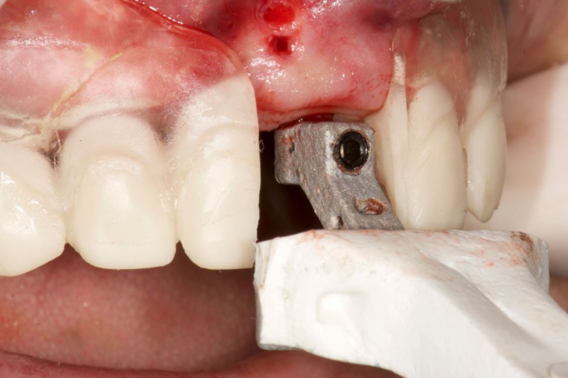
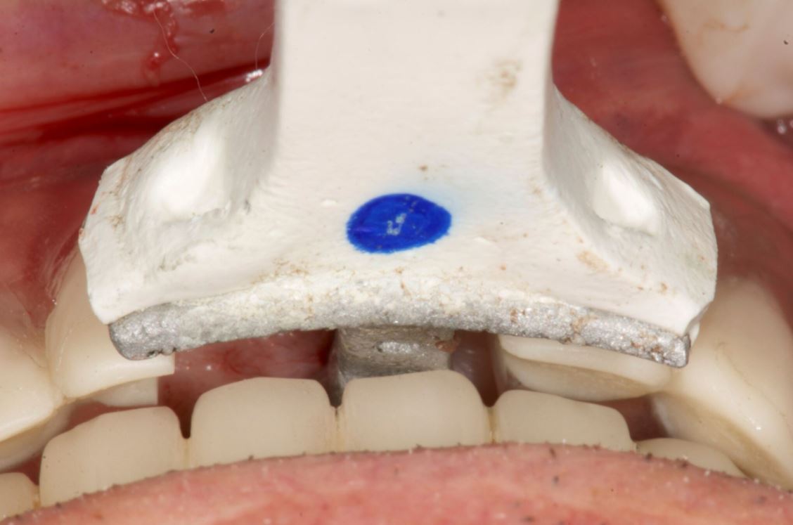
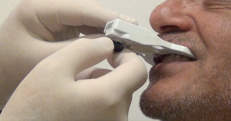
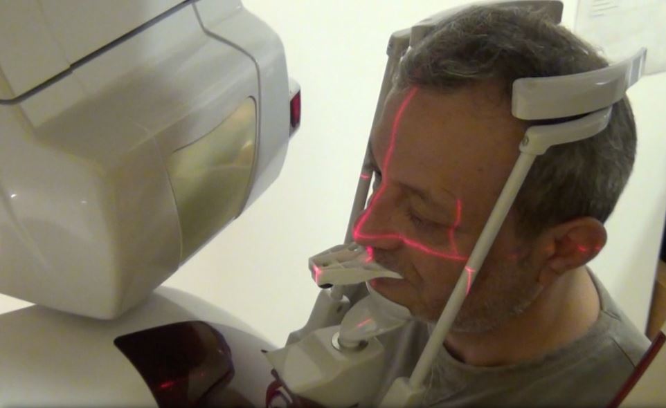
The NaviStent functions as a retainer onto which the CT marker is affixed to while the patient undergoes her CBCT scan. The NaviStent is a custom single use retainer made of a thermoplastic material called Naviplast than can be heated in hot water and molded to the patient’s dentition. The stent was trimmed and the planned implant site was cut open to expose the ridge. The CT marker was then fixed to the stent by way of a thumb screw. The NaviStent with the attached CT Marker was placed into the patient’s mouth. The stent was checked for stability in the patient’s mouth. A CBCT scan was completed for the entire maxillary arch being sure to include the arm of the CT marker which contains the aluminum fiducial.
The CBCT scan was then imported into the Navident software. The Navident software automatically registers the fiducial and asks you to inspect the registration to ensure there is no malalignment. Our implant position is prosthetically determined, so our first step was to place a virtual crown at the 2.5 (13) site. The vertical height of bone from the ridge to the sinus floor was measured using the software measuring tool and found to be 7.4mm (Fig 2).
Our treatment plan involved placing a Straumann Bone Level Tapered SLActive Roxolid 4.1mm x 10mm implant as a single stage flapless approach with an internal sinus elevation. Taking advantage of the freedom of the Navident system, we were able to plan our surgery to place a Straumann dental implant and complete our internal sinus lift using the HIOSSEN CAS-KIT (Crestal Approach Sinus Kit). To control our drilling depth and use the live navigation to guide us to the sinus, a digital implant was placed in the ideal location with respect to the digital crown. This digital plan would guide us to the sinus floor for the sinus elevation and allow ideal implant placement.
Live Navigation Implant Surgery and Internal Sinus Elevation.
The patient was seated for the implant surgery. Local anesthetic was given. The single use JawTag was fixated to the NaviStent with the provided thumb screw. The tag adapter was mounted onto the surgical handpiece and fastened in place according to the company’s instructions. The single use DrillTag was attached to the tag adapter on the surgical handpiece. The NaviStent was placed into the patient’s mouth with the JawTag visible for the Navident camera to detect. Once the CT markers are visible by the camera, they become visible on the side panel on the monitor. The next step was to calibrate the drill axis by placing the handpiece head onto the calibration peg present on top of the JawTag. The handpiece was then rotated back and forth around the peg to register and calibrate the drill axis. The system then prompts us to calibrate the drill. The initial precision point drill was then placed onto the handpiece and calibrated by placing the drill tip into the dimple present at the center of the target on the JawTag (Fig 3). Once the drill tip was calibrated, it then became visible on the monitor against the CT image when it is placed into the surgical field. Our next step was to verify the drill tip position. This was done easily by placing the tip of the bur on a landmark in the jaw to verify accuracy of its positioning. In our case the tip of the drill was verified by placing it on the cusp tip of the neighboring tooth 2.4 (13). The drill was then brought to the surgical site (Fig 4) and the navigated drilling screen comes up which shows a Target view and cross sectional views of the CT images with the drill image visualized in its real-time position (Fig 5). The target and cross sectional views allow you to position the drill into the ideal digitally planned implant position based on the live view of the drill over the CT images.
The drilling process was started with a precision drill to punch a dimple into the bone and give us a soft tissue bleeding point. The bleeding point was then used as a marker to remove a 4mm diameter of crestal gingiva with a tissue punch. The Straumann pilot drill was then calibrated and verified on the handpiece. The 2.2 mm pilot drill was then used to drill at 800rpm to about 7mm into the osteotomy using the live navigation to guide us into the digitally planned position. The second 2.8mm drill in the Straumann Bone Level Tapered implant protocol was calibrated, verified and live navigated to the desired position at a depth of 7mm into the osteotomy.
The drills were now switched to the Hiossen CAS-KIT drills to allow removal of the cortical bone at the floor of the sinus without damaging the Schneiderian membrane. The CAS-Drill tip has an inverse conical shape that forms conical bone chip as it drills to allow it to safely elevate the sinus membrane without perforating it. The bone particles formed when drilling discharge upwards producing a membrane auto-lift function. The Hiossen CAS 3.3mm drill was used with an 8mm stopper as a back up to prevent us from forcefully pushing too deep into the sinus. The CAS drill was calibrated and verified and then live navigated to access the sinus membrane.
Once the membrane was exposed through the osteotomy, it was elevated using hydraulic pressure with the CAS-Kit Membrane Lifter and sterile saline. Cortical allograft chips were then gentled pushed into the void created from the membrane elevation. The jaw stent was removed and the implant was placed through the osteotomy with direct vision. The Straumann Bone Level Tapered 4.1mm x 10mm implant was placed with 50Ncm of primary stability. A healing abutment was then hand torqued in place (Fig 6). A post-operative peri-apical radiograph (Fig 7) was taken to assess the implant placement. The implant can also be live navigated into place, however it needs to be calibrated by touching the tip of the implant over the JawTag dimple, and due to the risk of contamination we chose to place it with direct vision. The company recommends placing a sterile piece of nylon over the dimple when calibrating the implant to keep the conditions of the implant sterile.
Due to the flapless live guided Navident protocol, we were able to release the patient, with no sutures required and minimal trauma to the site. The patient was prescribed anti-inflammatory analgesics and placed on a 7 day antiobiotic course. Her healing was uneventful with minimal discomfort to the area.
Conclusion
Computer guided placement of dental implants is significantly more accurate than free hand surgery. In areas of complex anatomy, computer guided navigational surgery is superior to conventional implant surgery when it comes to preventing iatrogenic injuries. This technology can contribute to considerable improvement in quality and accuracy of dental implant placement. The live real-time view of the exact position of the drill minimizes the potential risk of damage to critical anatomic structures. The optical tracking system seems to be more accurate and have more flexibility during surgery but does require more training to develop hand eye coordination for using the system. However once mastered, this new system can improve on accuracy of surgery, reduce surgeon anxiety, improve patient confidence, and work as a powerful marketing tool for your practice.
About Naheed Mohamad
 Dr. Naheed Mohamed received his Honours Bachelor of Science degree from the University of Toronto. After a year of periodontal research at Mount Sinai Hospital, he attended dental school at Boston University and completed his Doctor of Dental Medicine degree. Graduating from dental school with magna cum laude and the American Academy of Periodontology Dental Student of the Year Award for achievement in Periodontics, Dr. Mohamed further pursued his studies at Case Western Reserve University in Cleveland to complete his specialty training in Periodontics. During his residency he pioneered research in an autologous blood derived material called platelet-rich fibrin and its numerous clinical applications; earning his Masters Degree. Dr. Mohamed is a board certified specialist in the United States and Canada attaining his Diplomate status by the American Board of Periodontology and Fellow of the Royal College of Dentists of Canada. Dr. Mohamed currently maintains a private practice and actively lectures about innovations in Periodontics and Implant surgery.
References
1. Rosenfeld AL, Mandelaris GA, Tardieu PB. Prosthetically directed implant placement using computer software to ensure precise placement and predictable prosthetic outcomes. Part 1: diagnostics, imaging, and collaborative accountability. Int J Periodontics Restorative Dent. 2006;26(3):215-221.
2. Buser D, Martin W, Belser UC. Optimizing esthetics for implant restorations in the anterior maxilla: Anatomic and surgical considerations. Int J Oral Maxillofac Implants. 19:(suppl):43-61
3. Jung RE, Schneider D, Ganeles J, Wismeijer D, Zwahlen M, Hammerle CH, & Tahmaseb A. (2009) Computer Technology applications in surgical implant dentistry: a systematic review. International Journal of Oral and Maxillofacial Implants 24(suppl.):92-109.
4. Cassetta M, Stefanelli LV, Giansanti M, et al. Depth deviation and occurrence of early surgical complications or unexpected events using a single stereolithographic surgi-guide. Int J Oral Maxillofac Surg. 2011;40(12):1377-1387.
5. Somogyi-Ganss E, Holmes HI, Jokstad A. Accuracy of a novel prototype dynamic computer-assisted surgery system. Clin. Oral Impl. 2014 May 19. doi: 10.1111/clr.12414
6. Accuracy of image-guided implantology. Brief J, Edinger D, Hassfeld S, Eggers G. Clin Oral Implants Res. 2005 Aug;16(4):495-501.
7. Computer-assisted navigational surgery enhances safety in dental implantology. Ng FC, Ho KH, Wexler A. Ann Acad Med Singapore. 2005 Jun;34(5):383-8
8. Clinical advantages of computer-guided implant placement: a systematic review. Hultin M, Svensson KG, Trulsson M. Clin Oral Implants Res. 2012 Oct;23 Suppl 6:124-35
9. Computer-aided manufacturing technologies for guided implant placement. Neugebauer J, Stachulla G, Ritter L, Dreiseidler T, Mischkowski RA, Keeve E, Zöller JE. Expert Rev Med Devices. 2010 Jan;7(1):113-29. doi: 10.1586/erd.09.61. Review.
“DYNAMIC NAVIGATION IN FULLY EDENTULOUS MAXILLA” BY PROF. DR HAKAN UYSAL & DR NOYAN BASAL, TURKEY 2017
Introduction
Preoperative planning is the most important part of a successful implant rehabilitation and requires multiple parameters to be considered for the precise placement of implants. The implants should be placed not only within anatomical boundaries but also be strategically located to support a prosthesis that will fulfil both functional and aesthetic requirements.
3-D virtual images are being used through computer software, which transforms CBCT scans into 3-D virtual models. However, after a precise planning or virtual realisation of the treatment, the osteotomy should also be executed precisely according to the plan and would likely require guidance of the drills and the implant.
For years, stereolithographic static guides have been used successfully for implant osteotomies, using detailed information implemented through 3-D virtual images.1,2 Static guides on the other hand present several disadvantages. The loss of tactile feeling during osteotomy and the fact of being limited to the predesigned drilling trajectory are considered to be their major drawbacks.
Real-time navigation
A recent technology, which provides dynamic guidance through a real-time navigation for implant osteotomy, offers not only accuracy, but also additional valuable advantages during an operation.3,4 With this technology, the location and diameter of implants can be modified and a flap can be incised intraoperatively whenever
needed.
Furthermore, dynamic navigation enables the surgeon to adjust the surgical plan during surgery. In case of an unexpected low bone quality, an additional implant could be planned with the software and placed additionally. Moreover, one of the most significant benefits of dynamic navigation is the ability to use it also for alveoloplasty and reshape the alveolar crest’s topography during the same surgery, together with the implant placement.
The precise location of implants is case-specific and determined by different factors. If an edentulous case is to be restored with an implant-supported screw-retained fixed prosthesis, implant locations should be critically examined whether they can provide screw access holes within occlusal or palatal/ lingual parts of the restoration. Frequently, alveoloplasty is required for the recontouring of the ridge in order to obtain sufficient bone thickness at the level of the implant’s collar. /
This crestal trimming of bone may also be necessary in order to increase the inter-arch space and provide a sufficient volume for the restorative material, since dentogingival prostheses are frequently required to enhance aesthetics. In such cases, dynamic guidance can be used to level the alveolar crests as planned on virtual images, followed by precise multiple osteotomies.
Case
The following case report describes the treatment of a 65-year-old male with an one-year history of maxillary partial edentulism (Fig. 1). He was discontent with the stability of his prosthesis and expressed that through the unstable prosthesis situation he has lost social self-confidence. In the initial appointment he thus stresses his need for a “fixed solution”.
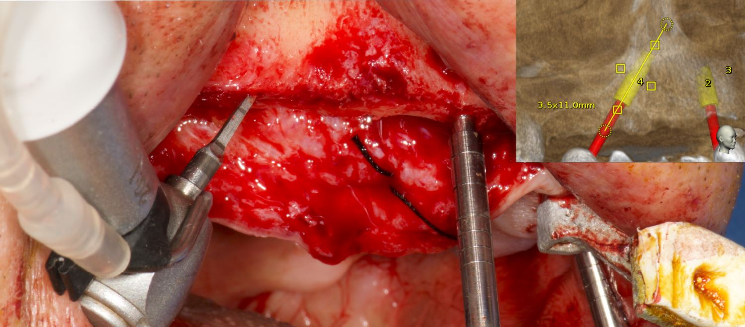
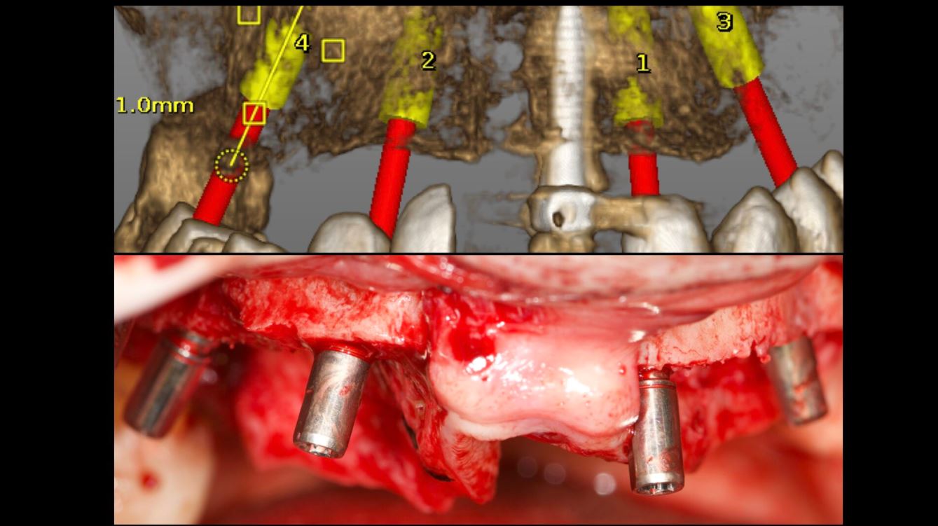
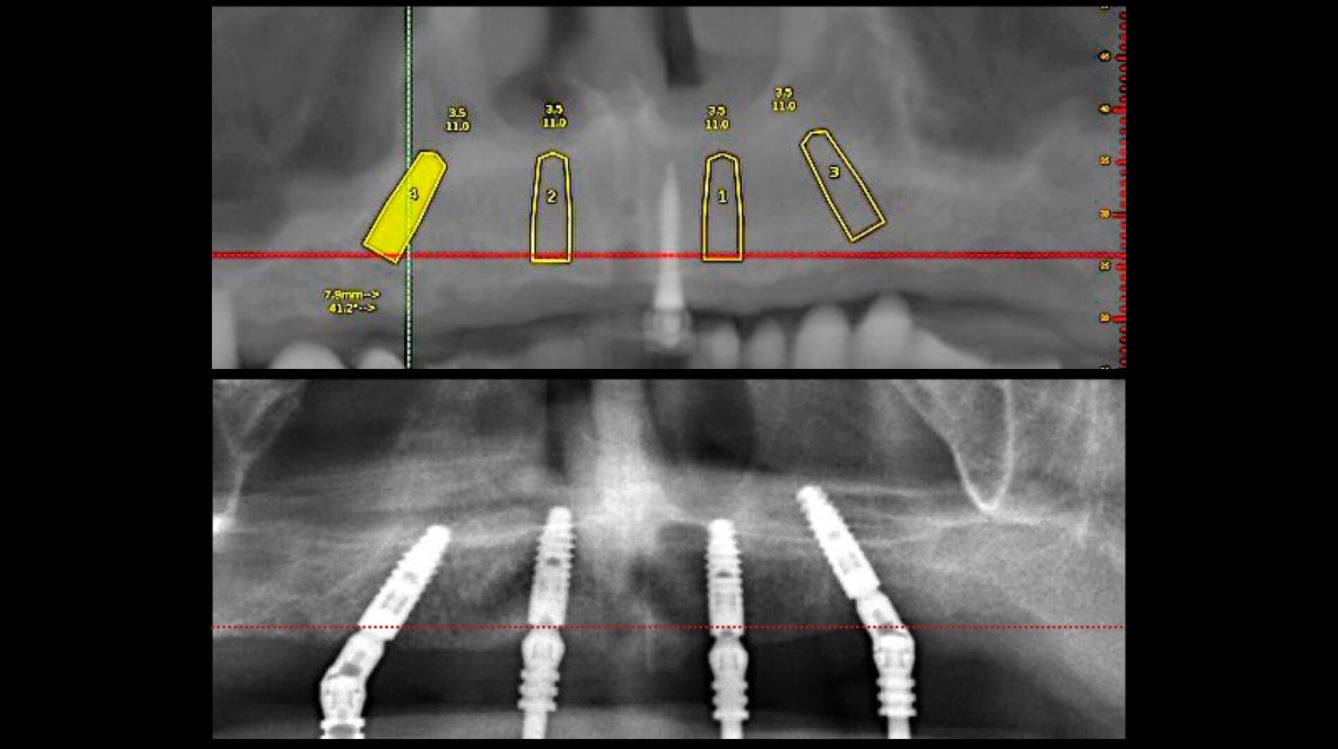
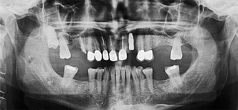
His medical history did not reveal any specific systemic disease or condition that contraindicates oral surgery. The patient’s soft tissues on the edentulous ridges were healthy and panoramic X-rays showed expanded sinuses at both sides and irregular alveolar ridges. The treatment plan, carried out for a maxillary screw-retained fixed prosthesis, included two implants at the pre-maxillary region and two tilted in the posterior maxilla to avoid a sinus lift surgery.
Stent placement
In order to acquire both anatomical and prosthetic information prior to the surgery, a scan prosthesis was manufactured by duplicating the maxillary denture (Fig. 2). It is important that the scan prosthesis has the same aesthetic and functional information as the complete denture or set-up. Thus, the scan prosthesis was checked for its fit, aesthetics and maxilla mandibular relation (Fig. 3). The scan prosthesis was then used together with a Navident Edentulous Kit for CBCT imaging.
The Navident edentulous protocol consists of a SDI (Small Diameter Implant of 2.2mm or 2.5mm diameter), which is inserted into the alveolar ridge of the arch to be operated, prior to the acquisition of the CT scan. This temporary SDI serves as a mount for the CT marker and for the Jaw Tag used for the registration of the CT scan to the patient and for tracking the patient’s jaw during surgery.
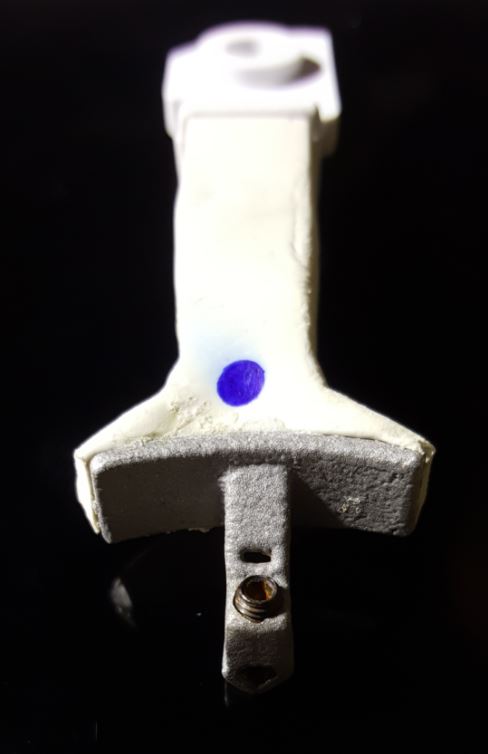
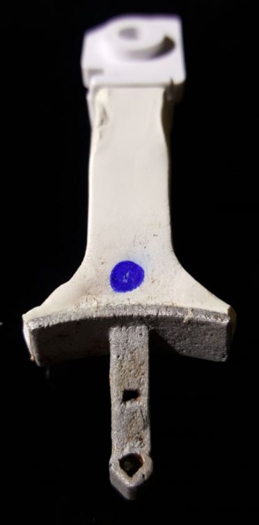
The SDI can be placed either in a vertical position or in a horizontal position in relation to the alveolar crest. A special plastic arm with a proprietary aluminium bracket is then used for the connection of the CT marker and Jaw Tag to the SDI. Two types of arms are available: one for a vertically placed and another for a horizontally placed SDI (Figs. 4a and b). In the presented case, the SDI has been placed vertically to achieve the required stability (Fig. 5).
The CT marker, containing the fiducial marker used for the registration of the CT scan to the patient, was attached to the V-type arm on the fix-plate at one end. At the other end, the assembly was placed over the SDI’s square head and secured to it using a setscrew which was embedded in the aluminium bracket, with this creating a complete “NaviStent” (Fig. 6).
The scan prosthesis was then modified to accommodate the aluminium bracket before it was placed over the maxillary edentulous ridge (Figs. 7 & 8). For accuracy purpose, it is imperative that the scan prosthesis is stable, while at the same time it should not interfere with the NaviStent.
CT scan
The following CBCT imaging protocol for Navident dynamic navigation was applied during CT imaging. Before the scanning procedures, both the modified scanning prosthesis and the NaviStent had been placed into the patient’s upper jaw (Figs. 9 & 10). A CT marker was then connected to the NaviStent. A scout view had been acquired prior to the actual scan to verify the presence of the CT marker in the CT scan. In order to allow for accurate registration, at least three corners of the fiducial marker must be present in the scan. In order to maintain a high level of accuracy during navigation, it is mandatory that the slice thickness must not exceed a maximum of 0.4mm. In this case, the slice thickness had been set to 0.3mm. Afterwards, the scan was exported in DICOM format, then imported into Navident.
Osteotomy planning
When the CT scan is imported into Navident, a proprietary algorithm detects the fiducial’s image in the scan, then registers it with a mathematical model of the fiducial that is stored in the computer memory. This enables Navident to map the Jaw Tag, which is the tag mounted onto the patient, to the CT image during navigation.
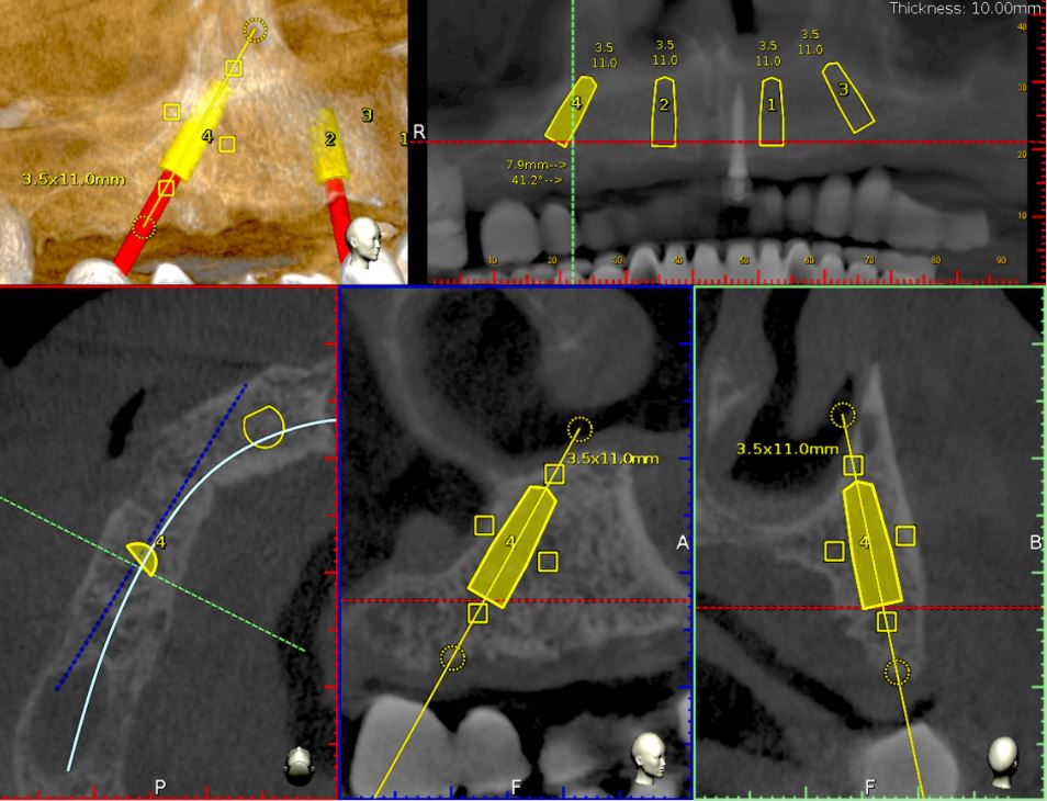
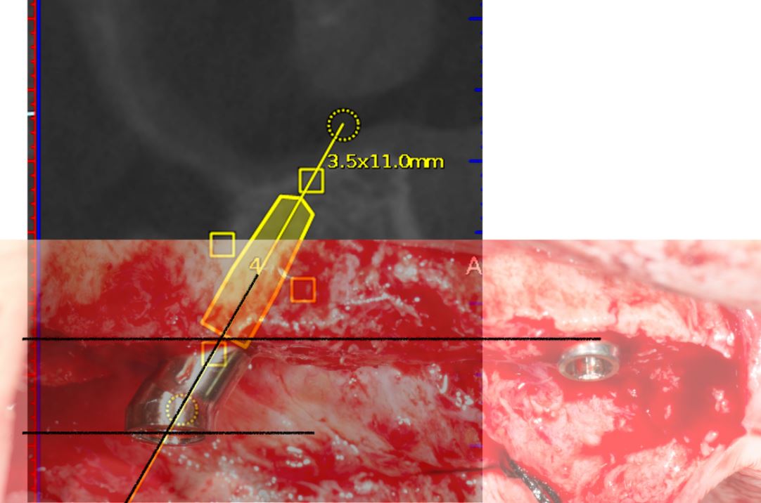
For this case, Ankylos dental implants had been selected. The implants with a diameter of 3.5mm and a length of 11mm were planned on the locations 15, 12, 22 and 25 using the Navident planning software (Fig. 11). The following parameters were considered when osteotomies were planned:
- Alveolar ridges, though they had a sufficient bone height, were narrowing at the crestal 1/3. Without waiving or compromising the restorative information, the implant locations were planned to be deeper where at least 2mm of buccal plate thickness could be achieved.
- Straight implants were placed at 12 and 22 and tilted ones at 15 and 25.
- Angulated distal implants were planned 1mm mesially to the sinus wall.
- The angle of distal abutments was planned to be 30 degrees to the occlusal plane to have the retaining screws access holes placed in the denture’s occlusal aspect since screw-retained abutments have 30-degree joints.
- The plane of the implant collars was planned to be parallel to the occlusal plane.
Surgery
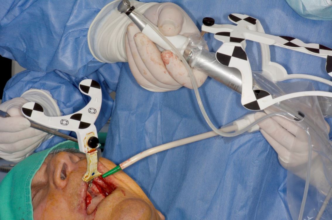
Before surgery, the CT marker was disconnected from the NaviStent Arm and replaced by the Jaw Tag, which is detected by the Navident camera. A Drill Tag was installed onto the handpiece (Fig. 12). Together with the Jaw Tag, they provide real-time feedback during surgery, enable the surgeon to communicate with the software and place the implant as planned.
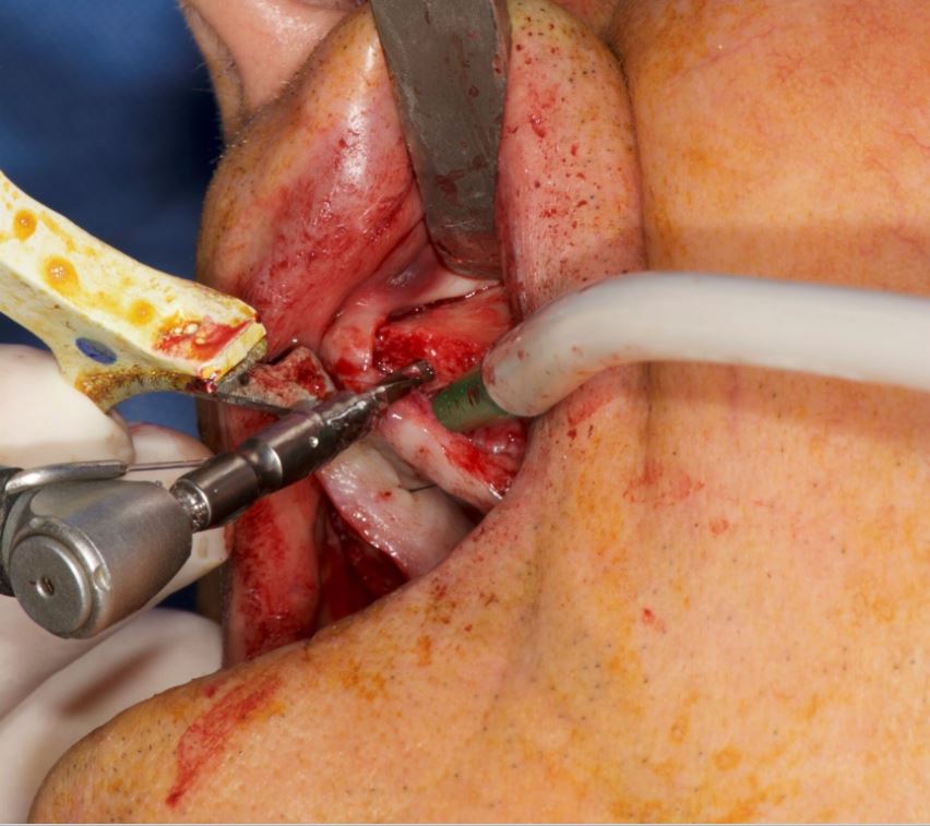
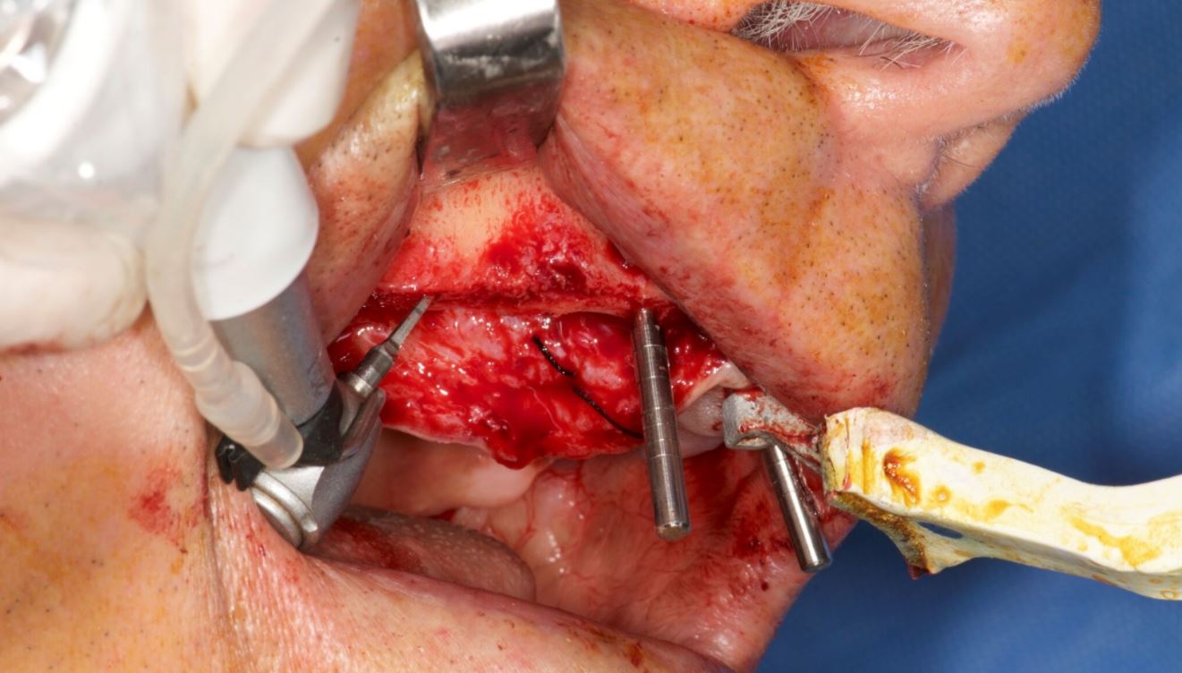
A crestal incision was made at either side. Pilot drills were used to start osteotomy followed by the Ankylos Dental Implant Drilling protocol. All drills were navigated according to the planned trajectory, until realtime feedback confirmed that its tip has reached the apical end of the planned osteotomy. The alveolar crests were levelled by a rongeur (Fig. 13). Between each trimming attempt, the pilot drill was touched to the trimmed surface of the crestal bone and its level was checked on the virtual image.
The trimming of the bone was completed under the guidance of dynamic navigation and the pilot drill was again touched to the newly formed alveolar crest. Implants were inserted in the osteotomies as planned, the gingival tissue placed back and sutured with coated poly-glactin 910 sutures. The patient was medicated with antibiotics and chlorhexidine mouth rinse and was released with NSAID’s (Figs. 14–16).
Conclusion
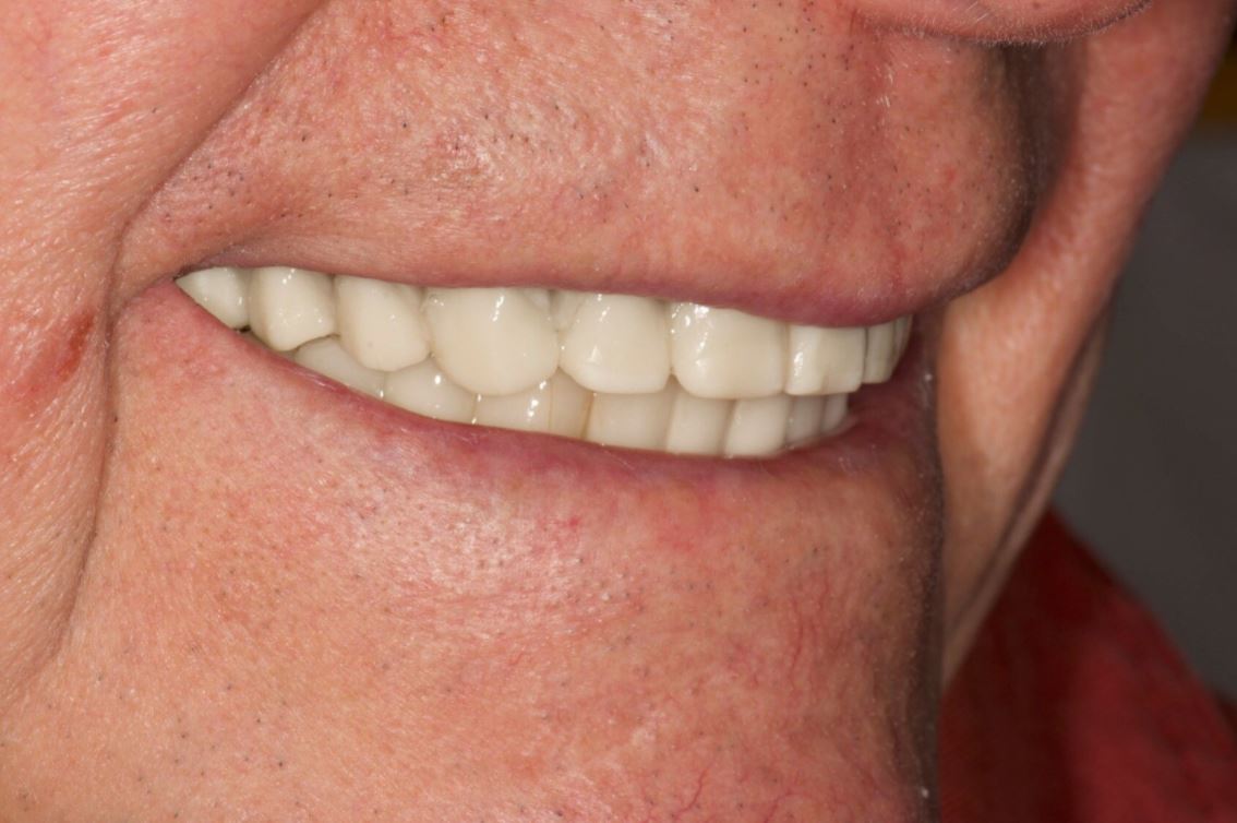
The Navident navigation surgery system achieves a successful guidance both in alveoloplasty and implant osteotomies in the edentulous maxilla (Figs. 17–19). In the presented case, the proposed protocol was highly efficient in gathering 3-D prosthetic and anatomical information for the planning. Dynamic navigation provided a precise guidance in the execution of the planned osteotomies through a flexible surgical operation.
References
1. D’haese J, Van De Velde T, Komiyama A, Hultin M, De Bruyn H. Accuracy and Complications Using Computer-Designed Stereo-lithographic Surgical Guides for Oral Rehabilitation by Means of Dental Implants: A Review of the Literature Clin Impl Dent Rel Res 2012; 14: 321–335.
2. Laleman I, Bernard L, Vercruyssen M, Jacobs R, Bornstein MM, Quirynen M. Guided Implant Surgery in the Edentulous Maxilla: A Systematic Review. Int J Oral Maxillofac Implants. 2016; 31 Suppl: s103-17.
3. Somogyi-Ganss E, Holmes HI, Jokstad A. Accuracy of a novel prototype dynamic computer-assisted surgery system. Clin Oral Implants Res. 2015 Aug;26(8):882-90.
4. Jung RE, Schneider D, Ganeles J, Wismeijer D, Zwahlen M, Hämmerle CH, Tahmaseb A. Computer technology applications in surgical implant dentistry: a systematic review. Int J Oral Maxillofac Implants. 2009;24 Suppl:92-109. Review.
Contact
Prof. Dr Hakan Uysal
DDS, PhD, Prosthodontist
Abdi Ipekci Cad. 61 Tesvikiye
Istanbul, Turkey
Tel.: +90 212 219 6744
[email protected]
Dr Noyan Basal
Klinik212 dental clinic
Valikonagi str. No:86/a
Nisantasi
Istanbul, Turkey
Tel.: +90 5324139118
[email protected]
"Use of Dynamic Navigation for Dental Implant Surgery" by Dr. Jan D’haese Ghent University March, 2015
INTRODUCTION
Although osseo-integration of dental implants is predictable1, thorough pre-operative planning is a prerequisite for a successful treatment outcome.2 Anatomic limitations as well as prosthetic considerations encourage the surgeon to obtain a very precise positioning of the implants. Historically, standard radiographic imaging techniques (intra-oral and panoramic) were available for investigation of potential implant sites. Throughout the years, spiral tomography and computed tomography (CT) were often used as a diagnostic tool.3 These techniques provide a 2-dimensional cross section image of the desired implant location and enables a detailed bucco-lingual view of the dimensions of the jawbone. Nowadays, it is well known that 3-dimensional CT scan based pictures allow a more reliable treatment planning than when only 2-dimensional data are available.4 Transforming the CT scan images into a 3D virtual image can be achieved using computer software packages,5 allowing for a 3D viewing using Computer Aided Design (CAD) technology. For years, stereolithographic guided surgery seemed to be the golden standard in computer guided implant surgery. The technique has been well developed over the last years and several scientific reports have been published regarding accuracy, complications, survival and success6. Real-time navigation seems to be a valuable alternative to stereolithographic (static) guided surgery as it offers the clinician some advantages compared to the former technique. Using real-time (dynamic) navigation one can avoid the fabrication of a stereolithographic template resulting in a less expensive treatment. As navigation is considered as a dynamic guided surgery system, changes to the treatment planning (location and size of the implants, number of the implants, flap or flapless…) can be easily made intra-operatively.
CASE PRESENTATIONS
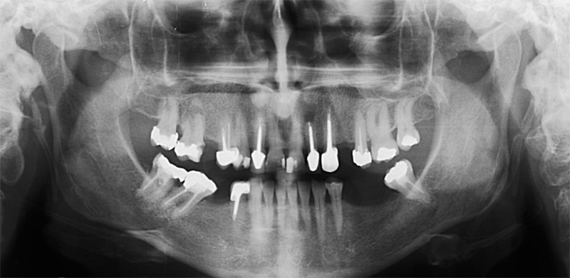
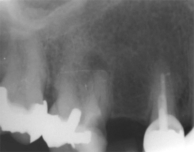
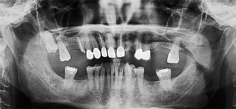
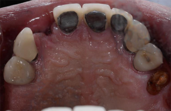
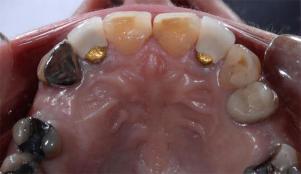
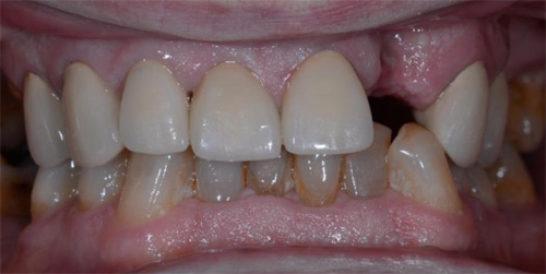
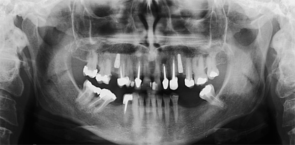
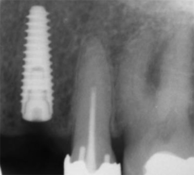
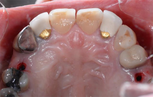
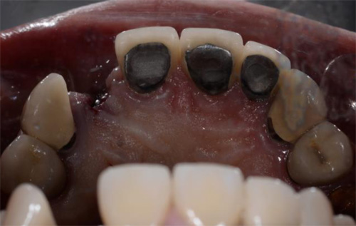
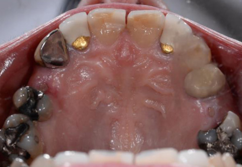
The first patient treated was a 59 year-old female consulting the dental office for replacement of two premolars in the maxilla, in locations 15 and 24 (Fig. 1, Fig. 2, Fig. 3). Patient was in good general condition and was a nonsmoker. Intraoral examination revealed numerous amalgam fillings and some metal-porcelain crowns (Fig. 4). Teeth 15 and 24 had to be extracted previously due to cariogenic process. Periodontal screening showed no signs of pathology. Treatment involved placement of 2 osseo-integrated implants in the edentulous regions of the maxilla.
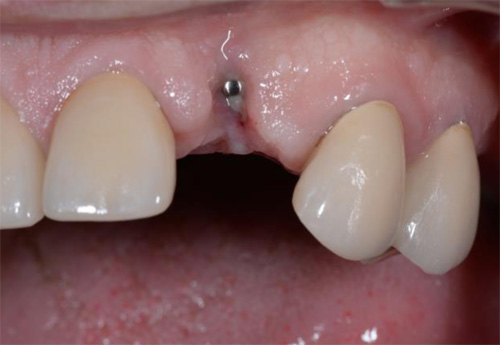
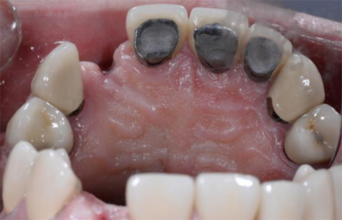
The second patient was a 55 year-old male visiting the office to restore a recently extracted lateral incisor (Fig. 5, Fig. 6). He was a non-smoker, in good general health and not suffering from any systemic disease. Intra-oral examination showed several crowns in the maxilla and a residual root fragment in location 15 (Fig. 7, Fig. 8). Patient suffered from moderate periodontal breakdown. This periodontal condition has been present yet stable for several years.
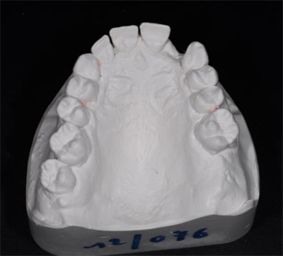
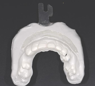
For both of the patients, impressions of the dental arch were taken prior to implant installation using an irreversible hydrocolloid (Cavex CA37, fast set, Cavex Holland BV, Haarlem, The Netherlands) to fabricate a diagnostic cast (Fig. 9). This cast was used as a model for the molding of theNaviStent in order to have a perfect fit. The NaviStent serves as scanning template and is worn by the patient during the scanning procedure and the surgery. (Fig. 10).
Afterwards, the patient was sent to the CBCT and a scan was made with the NaviStent in place.
PLANNING PROCEDURE
A standard CBCT scan was performed according to the procedure outlined in the scanning protocol by Navident (Navident, Toronto, Canada).
The CBCT images were converted into a DICOM image (digital imaging and communications in medicine) and transformed into a 3-D virtual model using the Navident software system. The clinician who placed the virtual implants in the resulting 3-dimensional model also performed the actual surgeries. The potential locations for implant placement, and corresponding implant lengths and widths were planned in a prosthetically driven way. A distance of at least 3 mm from the neck of implant to the gingival zenith was applied, allowing the biological width to create a connective tissue contour around the abutments.
SURGICAL PROCEDURE
The surgery was performed under local-regional anaesthesia. Appropriate aseptic and sterile conditions prevented post-operative infections. During the operation, the NaviStent was placed over the remaining teeth (Fig. 11). The NaviStent was primarily fixated around the undercuts of the remaining teeth and additionally by application of a denture adhesive (prothese kleefcreme).
The osteotomies were prepared at maximum of 1500 rpm using the Navident navigation system to guide the drilling procedure in real-time by indicating the desired drilling pathway on the computer screen. Prior to the use of each new drill, a calibration process is performed (Fig. 12). No punching of the gingival tissues was performed prior to the preparation of the implant sites.
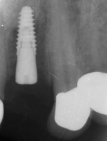
In the first patient, 2 Xpeed® Anyridge® implants (Megagen, Seoul, South-Korea) were installed. At locus 15; a 10 mm length and a 4 mm wide fixture was inserted whereas at locus 24 a 13 mm length and a 3,5 mm diameter wide implant was installed (Fig. 13, Fig. 14, Fig. 15).
In the second patient, a solitaire Xpeed® Anyridge® implant with a length of 10 mm and a diameter of 3,5 mm was placed at locus 22 (Fig. 16, Fig. 17). An Xpeed® Anyridge® implant consists of a nanolayer of calcium ions incorporated on the sandblasted, large-grit, acid-etched (SLA) implant surface. All the implants were inserted into the maxilla with a maximum insertion torque of 35 Ncm.
As the implant fixtures were also calibrated for use with the navigation system (Fig. 18), their exact position could also be tracked during insertion. This means that both implant preparation drilling and the implant placement process are tracked in real time. Depth of drilling and placement are guided by Navident using on screen visual representation and auditory cues to aid the clinician. Immediately after implantation, cover screws were placed onto the implants and hand torqued (Fig. 19, Fig. 20).
Postoperatively, patient received a prescription for antibiotics (amoxicilline 1000 mg, 2x/d, 4 days), for non-steroidal anti-inflammatory drugs (ibuprofen 600mg, 3x/d) and for a mouthwash (chlorhexidine 0,12%, 2x/d). After 1 week, a post-operative visit was scheduled. No signs of infection or inflammation were present as the healing went on uneventfully (Fig. 21, Fig. 22, Fig. 23).
CONCLUSIONS
In a one week postoperative follow up the patients reported no pain or swelling associated with the dental implant procedure. Further postoperative results are being tracked and reported as part of a qualitative study being done in cooperation with the University of Ghent. The potential of the Navident dynamic navigation system with regard to minimally invasive and accurate implant surgeries will be evaluated during this study.
REFERENCES
1. Albrektsson T, Dahl E, Enbom L, et al. Osseointegrated oral implants. A Swedish multicenter study of 8139 consecutively inserted Nobelpharma implants. J Periodontol 1988; 59:287–296.
2. Jacobs R, Adriansens A, Naert I, Quirynen M, Hermans R, van Steenberghe D. Predictability of reformatted computed tomography for preoperative planning of endosseous implants. Dentomaxillofacial Radiology 1999; 28,37–41.
3. Rothman SL, Chaftez N, Rhodes ML, Schwarz MS. CT in the preoperative assessment of the mandible and maxilla for endosseous implant surgery. Work in progress. Radiology 1988; 168:171–175.
4. Jacobs, R., Adriansens, A., Verstreken, K., Suetens, P. & van Steenberghe, D. Predictability of a three-dimensional planning system for oral implant surgery. Dentomaxillofacial Radiology 1999; 28:105–111.
5. Israelson H, Plemons JM, Watkins P, Sory C. Barium-coated surgical stents and computer- assisted tomography in the preoperative assessment of dental implant patients. Int J Periodontics Restorative Dent 1992; 12:52–61.
6. D’haese J, Van De Velde T, Komiyama A, Hultin M, De Bruyn H. Accuracy and Complications Using Computer-Designed Stereolithographic Surgical Guides for Oral Rehabilitation by Means of Dental Implants: A Review of the Literature Clin Impl Dent Rel Res 2012; 14: 321–335
Navident is cleared by the FDA for sale in the United States. Navident is approved for commercial sales and distribution in Canada by Health Canada. It has also received the CE mark; please contact ClaroNav.
Input the main text content for your module here.


